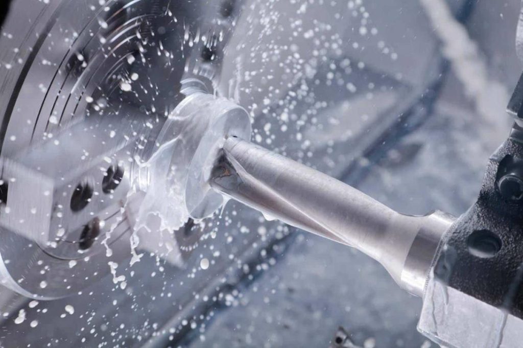

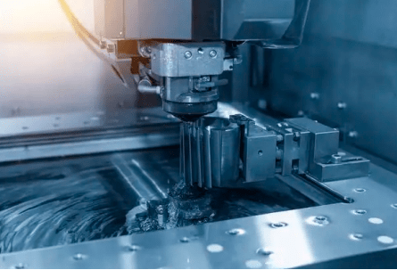
Computer Numerical Control (CNC) machining has emerged as a cornerstone of precision and efficiency. This technology, driven by sophisticated software and advanced machinery, allows for the automated creation of intricate components with unparalleled accuracy and repeatability. To fully grasp the intricacies of this transformative field, a solid understanding of key terminology is essential. This article aims to demystify the world of CNC machining by exploring fundamental concepts, including Computer-Aided Design (CAD), Computer-Aided Manufacturing (CAM), Distributed Numerical Control (DNC), Manufacturing Data Collection (MDC), and the crucial role of G-code and M-code in driving machine operations.
Computer-Aided Design (CAD)
CAD is essentially the digital blueprint of a physical object. CAD software allows engineers and designers to create precise, three-dimensional (3D) models of objects on a computer screen. These models can be rotated, zoomed, and manipulated in various ways, allowing for thorough examination and modification before any physical production begins.
Purpose:
Product Design: CAD is the foundation of modern product design. Engineers use it to:
- Conceptualize and visualize: Explore various design options, test different shapes and sizes, and quickly iterate on ideas.
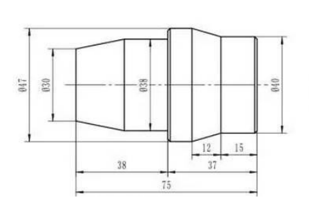
- Create detailed drawings: Generate precise blueprints, including dimensions, tolerances, and other critical manufacturing information.
- Perform simulations: Analyze the performance of a design, such as its strength, stress distribution, and fluid flow, before it’s even built.
Assembly Design: CAD enables the design of complex assemblies with multiple parts. It allows designers to:
- Assemble virtual prototypes: Simulate how parts fit together, identify potential interference issues, and ensure proper function.
- Create assembly drawings: Generate detailed instructions for manufacturing and assembly.
Popular Software:
- AutoCAD: A widely used and industry-standard 2D/3D CAD software known for its versatility and powerful features.
- SolidWorks: A popular 3D CAD software that excels in mechanical design, offering a user-friendly interface and advanced capabilities.
- FreeCAD: A free and open-source 3D CAD software suitable for a wide range of applications, from mechanical engineering to architecture.
Relationship to CNC:
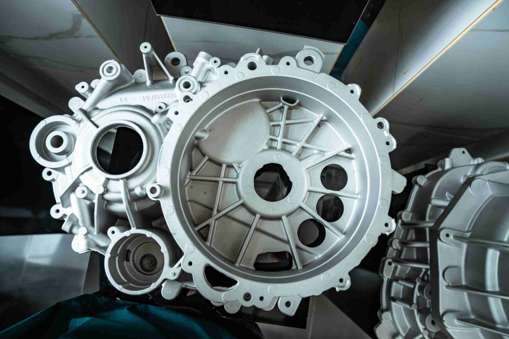
CAD models are the starting point for CNC machining. The 3D model provides all the necessary information about the part’s geometry, including its shape, dimensions, and surface features. This data is then used by CAM (Computer-Aided Manufacturing) software to generate the instructions (G-code and M-code) that tell the CNC machine how to cut the part from the raw material.
Computer-Aided Manufacturing (CAM)
CAM software acts as the bridge between the digital design world of CAD and the physical world of CNC machining. It takes the 3D model created in CAD and translates it into a set of instructions (G-code and M-code) that the CNC machine can understand and execute. Essentially, CAM software tells the machine:
- What tools to use: Selecting appropriate cutting tools (e.g., drills, mills, routers) based on the material and the desired features.
- How to move the tools: Defining the precise paths that the cutting tools should follow to remove material and create the desired shape.
- The speed and feed rates: Determining the optimal cutting speed and feed rate for each operation to ensure efficiency and prevent tool wear.
Process:
Import CAD Model: The CAM software imports the 3D CAD model of the part.
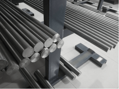
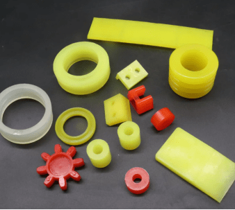
Define Workpiece: The user defines the raw material (e.g., block of metal, plastic) and its dimensions.
Select Machining Operations: The user chooses the necessary machining operations, such as milling, drilling, and turning.
Define Toolpaths: The CAM software generates the toolpaths, which are the specific movements that the cutting tools will make to create the part. This often involves:
- Roughing: Removing the majority of the excess material quickly.
- Finishing: Creating the final, precise shape and surface finish.
Simulate Machining: The CAM software allows for a virtual simulation of the machining process. This helps identify potential collisions, optimize toolpaths, and minimize machining time.
Generate G-code: The CAM software generates the G-code and M-code instructions that control the CNC machine’s movements and operations.
Post-processing: The G-code is often post-processed to adapt it to the specific requirements of the CNC machine and its control system.
Key Features of CAM Software:
- Simulation: As mentioned, simulation capabilities are crucial for visualizing the machining process, identifying potential issues, and optimizing toolpaths.
- Optimization: CAM software incorporates algorithms to optimize cutting parameters (speed, feed rate) to maximize material removal rates, minimize cycle times, and reduce tool wear.
- Toolpath Strategies: Advanced CAM software offers a variety of toolpath strategies, such as high-speed machining, 3-axis milling, 5-axis machining, and simultaneous 5-axis machining, to accommodate complex geometries and improve efficiency.
- Automation: Many CAM systems offer features to automate repetitive tasks, such as creating fixtures, generating tool lists, and optimizing cutting parameters.
- Integration with CAD: Seamless integration with CAD software allows for a smooth workflow and minimizes data transfer issues.
Distributed Numerical Control (DNC)
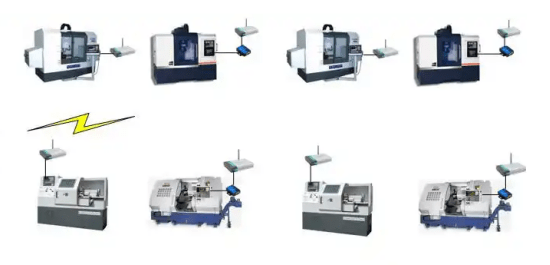
DNC systems connect multiple CNC machines to a central computer. This central computer acts as a hub, storing and managing all the CNC programs (G-code and M-code) that control the machines. Instead of manually loading programs onto each machine individually (using methods like memory cards or USB drives), the programs are transmitted directly from the central computer to the machines over a network.
Benefits:
Increased Efficiency:
- Reduced Setup Time: DNC eliminates the time-consuming process of manually loading programs onto each machine.
- Faster Program Distribution: Programs can be quickly distributed to multiple machines simultaneously, significantly speeding up production cycles.
- Improved Machine Utilization: With faster program distribution, machines can be kept running more consistently, maximizing production output.
Enhanced Flexibility:
- Centralized Program Management: All programs are stored centrally, making it easier to manage, back up, and share programs across the network.
- Quick Program Changes: Changes to programs can be easily made and distributed to all affected machines quickly, improving responsiveness to design changes or production adjustments.
- Remote Monitoring: DNC systems often allow for remote monitoring of machine status, allowing for proactive maintenance and troubleshooting.
Applications:
DNC systems are particularly beneficial in manufacturing environments with:
- High-volume production: Where maximizing machine utilization and minimizing downtime are critical.
- Frequent program changes: Such as in industries with frequent product design updates or short production runs.
- Multiple CNC machines: Where managing and distributing programs to numerous machines can be a logistical challenge.
Examples of Industries:
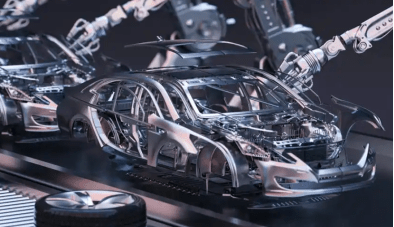
- Automotive: Mass production of vehicle components.
- Aerospace: Manufacturing of complex aircraft parts.
- Electronics: Production of printed circuit boards and other electronic components.
- Medical device manufacturing: Producing high-precision medical implants and instruments.
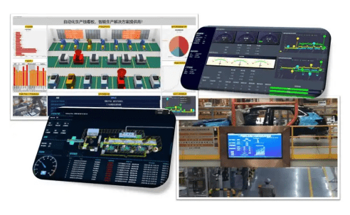
Manufacturing Data Collection (MDC)
MDC refers to the automated collection of data from various sources within a manufacturing environment. These sources can include:
- CNC machines: Data points collected directly from the machines include operating times, downtimes, production volumes, tool wear, and energy consumption.
- Sensors: Sensors can monitor various aspects of the manufacturing process, such as temperature, vibration, and pressure.
- Operators: Data can be collected from operator inputs, such as job start/stop times, material usage, and quality inspections.
Benefits:
Improved Process Optimization:
- Identify Bottlenecks: By analyzing data on machine downtime, production bottlenecks can be quickly identified and addressed.
- Optimize Production Schedules: Data-driven insights can help optimize production schedules, improve material flow, and minimize lead times.
- Enhance Quality Control: Monitoring key process parameters helps ensure consistent product quality and reduce defects.
Reduced Downtime:
- Predictive Maintenance: By analyzing sensor data, potential equipment failures can be predicted and prevented, minimizing unplanned downtime.
- Faster Troubleshooting: Real-time data can help quickly diagnose and resolve equipment malfunctions, reducing downtime and repair costs.
Enhanced Quality:
- Process Control: Continuous monitoring of key process parameters allows for real-time adjustments to maintain consistent product quality.
- Data-Driven Quality Improvement: Analyzing historical data can identify root causes of quality issues and implement corrective actions.
Applications:
- Process Monitoring: Real-time monitoring of key process parameters, such as temperature, pressure, and vibration, allows for early detection of anomalies and potential problems.
- Predictive Maintenance: Analyzing sensor data from machines can predict potential equipment failures before they occur, allowing for proactive maintenance and minimizing downtime.
- Overall Equipment Effectiveness (OEE) Calculation: MDC data can be used to calculate OEE, a key performance indicator that measures the overall effectiveness of equipment utilization.
- Quality Control: Collecting data on key quality characteristics, such as dimensions, tolerances, and surface finish, helps to identify and address quality issues.
- Energy Management: Monitoring energy consumption of machines and equipment can help identify areas for energy savings and reduce operating costs.
G-code and M-code
G-code:
Stands for “Geometric code.” These are the core instructions that control the movement of the CNC machine’s cutting tools. They define the path the tool will take, including linear movements, circular arcs, and other geometric shapes.
- Position the tool: Move the tool to specific locations on the workpiece.
- Define cutting paths: Determine the exact path the tool will follow to create the desired shape.
- Control feed rates: Adjust the speed at which the tool moves along the cutting path.
Typically starts with the letter “G” followed by a number (e.g., G00, G01, G02). Includes parameters that specify coordinates (X, Y, Z) for tool movement, feed rates (F), and other relevant information.
Example: G01 X10.0 Y5.0 F100 (Move linearly to X=10, Y=5 at a feed rate of 100 units/minute)
M-code:
Stands for “Miscellaneous code.” These codes control auxiliary functions of the CNC machine that don’t directly involve tool movement.
- Start/Stop spindle: Turn the spindle on and off.
- Control coolant: Turn coolant on and off.
- Change tools: Select and change tools in the tool magazine.
- Program start/stop: Initiate and end the program execution.
Starts with the letter “M” followed by a number (e.g., M03, M05, M30). Often has no additional parameters, although some M-codes may have optional parameters.
Example: M03 (Start spindle clockwise)
Key Takeaways
This article by CNC machining service expert JTR has explored several key terms essential for understanding the principles of CNC machining. We began by examining CAD and CAM, highlighting how these software tools form the foundation of the CNC process, transforming digital designs into executable machine instructions. We then delved into DNC systems, which enhance efficiency by enabling the centralized management and distribution of CNC programs. The importance of MDC in collecting and analyzing data from the manufacturing process was also emphasized, showcasing its role in improving productivity, reducing downtime, and enhancing product quality. Finally, we dissected the critical role of G-code and M-code, the languages that instruct the CNC machine on how to move, cut, and perform auxiliary functions.