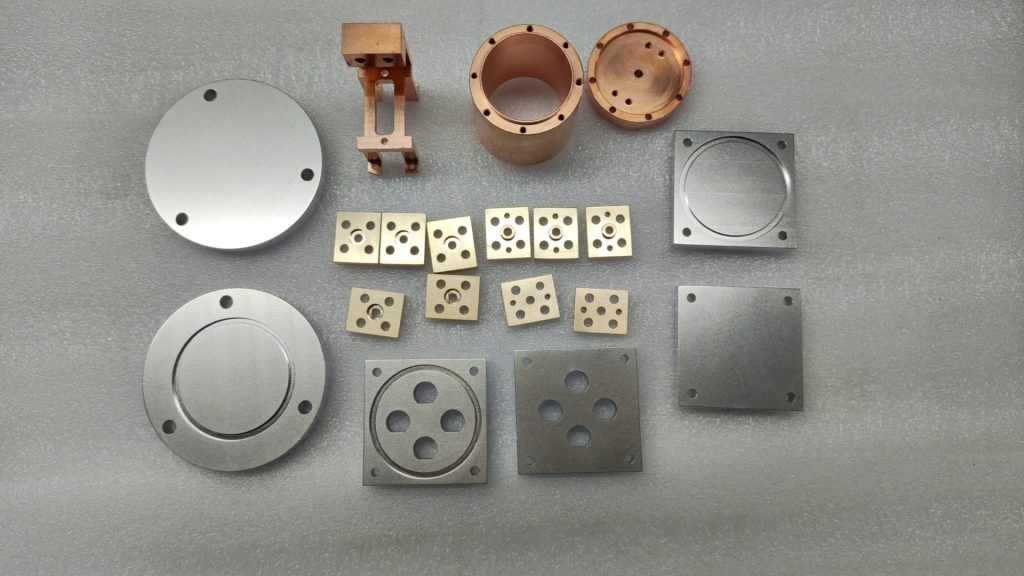
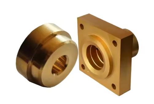
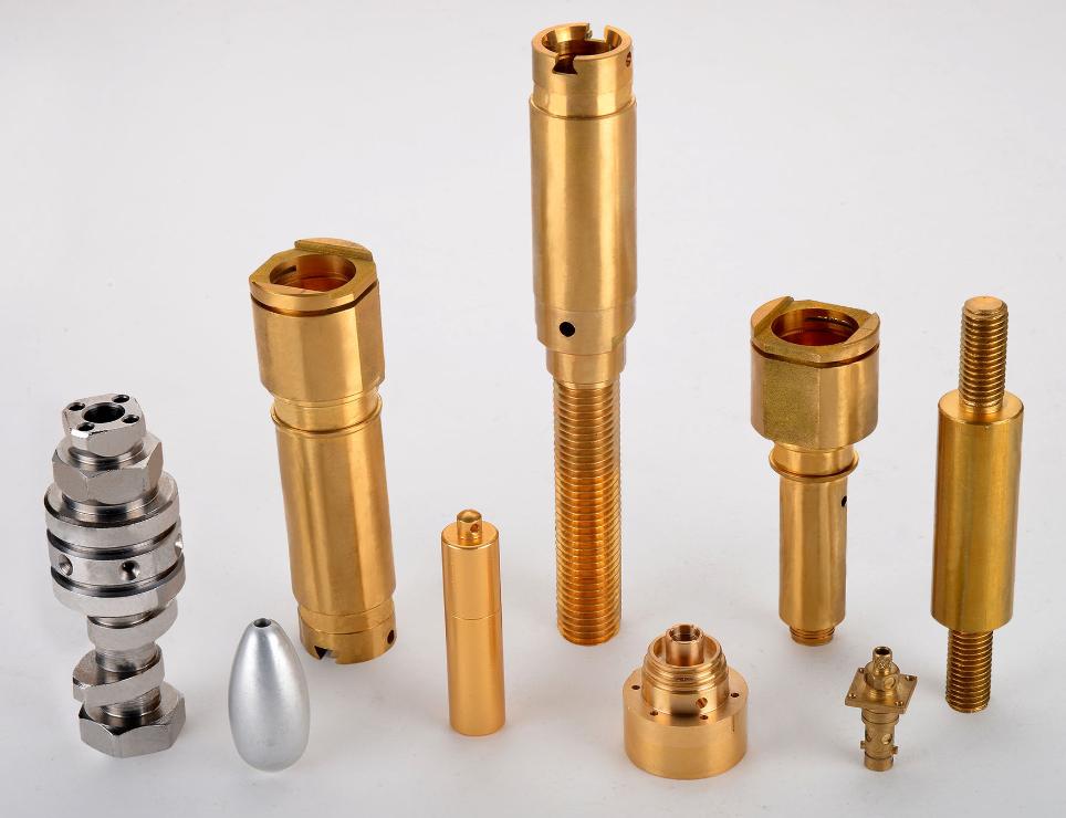
Brass and copper are widely used in various industries due to their excellent electrical conductivity, corrosion resistance, and machinability. These materials are commonly processed using CNC machining to create intricate components with high precision and efficiency. Selecting appropriate cutting parameters is crucial for achieving optimal results in the CNC machining of brass and copper.

Factors Affecting the Selection of Cutting Parameters
1. Material Properties
The hardness, ductility, and other properties of brass and copper significantly influence the selection of cutting parameters. Different types of brass and copper alloys exhibit varying characteristics.
- Hardness: Harder materials generally require lower cutting speeds and feed rates to prevent excessive tool wear and heat generation.
- Ductility: Ductile materials, such as annealed copper, can withstand higher cutting forces and allow for larger depths of cut.
- Thermal conductivity: Materials with high thermal conductivity, like copper, are more susceptible to thermal shock. Adequate cooling is essential to prevent tool failure and workpiece distortion.
- Alloy composition: The presence of alloying elements can affect the machinability of brass and copper. For example, alloys with higher zinc content may be more prone to work hardening.
2. Tool-Related Factors
The type of cutting tool and its geometry and coating play a crucial role in determining the optimal cutting parameters.
2.1 Tool material:
- Cemented carbide: Offers excellent wear resistance and is commonly used for finishing operations on brass and copper.
- High-speed steel (HSS): More versatile and cost-effective than carbide, but may have limited tool life at high cutting speeds.
- Ceramic: Provides excellent wear resistance at high temperatures but is more brittle than carbide.
2.2 Tool geometry:
- Rake angle: Affects the cutting forces and chip formation. A positive rake angle can reduce cutting forces but may increase tool wear.
- Clearance angle: Provides clearance for the chip to flow and prevents rubbing between the tool and workpiece.
- Nose radius: Influences the surface finish and tool life. A larger nose radius generally produces a better surface finish but may increase cutting forces.
2.2 Tool coating:
- TiN, TiCN, and AlTiN coatings: Improve wear resistance, reduce friction, and enhance tool life.
- DLC coatings: Provide excellent wear resistance and low friction, but are more expensive than other coatings.
Selection of Primary Cutting Parameters
1. Cutting Speed
The recommended cutting speed range for brass and copper is typically between 60 and 120 m/min. This range is influenced by factors such as material hardness, tool geometry, and desired surface finish. A higher cutting speed can increase productivity but may also lead to increased tool wear and reduced tool life. Conversely, a lower cutting speed can improve tool life but may decrease productivity. The optimal cutting speed should be selected based on a balance of these factors and the specific requirements of the machining operation.
For example, when machining for high precision, a lower cutting speed may be necessary to minimize thermal distortion and improve surface finish. On the other hand, for roughing operations, a higher cutting speed can be used to remove material more quickly.
2. Feed Rate
A suitable feed rate range for brass and copper is typically between 0.1 and 0.25 mm/rev. The feed rate affects the chip thickness, tool wear, and surface finish. A higher feed rate can increase material removal rate but may also lead to increased cutting forces, vibration, and poor surface finish. Conversely, a lower feed rate can improve surface finish but may decrease productivity.
The choice of feed rate should also consider the tool geometry and the desired chip thickness. A smaller nose radius on the cutting tool may require a lower feed rate to prevent excessive tool wear. Additionally, a thicker chip may be desirable for roughing operations, while a thinner chip may be preferred for finishing operations.
3. Depth of Cut
A suggested depth of cut range for brass and copper is between 0.15 and 0.25 mm. The depth of cut is related to the material removal rate, tool life, and processing accuracy. A larger depth of cut can increase productivity but may also lead to increased deflection, vibration, and tool wear. Conversely, a smaller depth of cut can improve accuracy but may decrease productivity.
The optimal depth of cut should be selected based on the workpiece material, tool geometry, and machine tool capabilities. A more rigid machine tool can accommodate a larger depth of cut without sacrificing accuracy. Additionally, a sharper cutting tool can handle a larger depth of cut before experiencing excessive wear.
Other Relevant Parameters
1. Tool Rake Angle
The recommended tool rake angle for machining brass and copper is typically between 6 and 8 degrees. The rake angle is the angle between the face of the cutting tool and a plane perpendicular to the workpiece. A positive rake angle can reduce cutting forces, improve chip flow, and reduce tool wear. However, an excessively large rake angle can weaken the cutting edge and increase the risk of tool breakage.
- Impact on cutting forces: A positive rake angle reduces the component of the cutting force that acts to push the tool away from the workpiece, resulting in lower overall cutting forces.
- Impact on tool wear: A positive rake angle can help to reduce friction between the tool and the workpiece, which can prolong tool life.
2. Coolant Usage
Coolant plays a crucial role the in CNC machining of brass and copper. It serves several purposes:
- Cooling: Coolant helps to dissipate the heat generated during the machining process, preventing excessive tool wear and workpiece distortion.
- Lubrication: Coolant reduces friction between the tool and the workpiece, improving tool life and surface finish.
- Chip evacuation: Coolant helps to flush away chips from the cutting zone, preventing chip re-cutting and improving surface finish.

Consideration of Machining Methods
1. Characteristics of Different Machining Methods
The choice of machining method, such as side milling, significantly impacts the selection of cutting parameters. Different machining methods have unique characteristics that influence how the workpiece is removed.
- Side milling: In side milling, the cutter’s axis is perpendicular to the workpiece surface. This method is often used for slotting, profiling, and pocketing operations. The cutting forces and chip formation are different from face milling, and the selection of cutting parameters must be adjusted accordingly.
2. Impact of Machining Method on Cutting Parameter Selection
The machining method directly affects the cutting forces, chip formation, and heat generation. Consequently, the optimal cutting parameters will vary depending on the chosen method.
- Cutting forces: Different machining methods generate different cutting forces. For example, side milling typically produces higher radial forces compared to face milling. This can affect the stability of the machining process and the selection of feed rate and depth of cut.
- Chip formation: The shape and size of the chips produced can vary depending on the machining method. This can impact the tool life and the overall efficiency of the machining process. For instance, side milling often produces longer, thinner chips compared to face milling.
- Heat generation: The distribution of heat generated during machining can differ between different methods. This can affect the thermal expansion of the workpiece and the risk of tool wear.
The Importance of Flexibility
It is essential to recognize that the optimal cutting parameters may vary depending on the specific machining conditions and desired results. Test cutting is a valuable tool for validating parameter selections and making necessary adjustments. By carefully considering the factors discussed above and conducting thorough test cuts, machinists can achieve optimal machining performance and produce high-quality components.
In conclusion, selecting the right cutting parameters for CNC machining brass and copper requires a balance of various factors. Machinists should adopt a flexible approach, continuously evaluating and adjusting parameters based on the specific requirements of each job.
For more information, you can consult with the CNC machining service provider JTR.


